Wednesday, 22 October 2014

DTMF based Home Automation System using Microcontroller

DTMF based Home Automation System using Microcontroller


Normally, many home appliances can be controlled by switches. But, nowadays we often see the automation of home appliances using many technologies. This article presents the DTMF based home automation system using microcontroller. Dual Tone Multi Frequency (DTMF) is a signaling system for identifying the keys on a DTMF keypad. It is used for telecommunication signaling over analog telephone lines in the voice frequency band between communication devices and telephone handsets.
DTMF is a short form of Dual Tone Multi Frequency. So, when you make a call to a customer care, they will ask you to press any number. When you press any number from your mobile, one particular action takes place because of dual tone multi frequency. When a button is pressed from the mobile keypad, the act immediately generates a tone of two frequencies. These tones are called column and row frequencies.
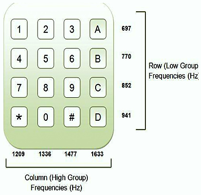
DTMF keypad
DTMF keypad
 Here, in the above depicted figure,the column frequencies are high frequencies, and the row frequencies are low frequencies. These row and column frequencies are selected for DTMF in such a way that they don’t have harmonic relation with the others. As a result, they will not generate same tones. The row frequencies are somewhat lower than the column frequencies.

Types of RAM Memories:

Static Random Access Memory

Types of RAM Memories:

RAM memory classified into two types of memories such as SRAM and DRAM memory.

SRAM (Static Random Access Memory):

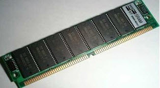
Static Random Access Memory is a type of RAM that retains the information in its memory as long as power is being supplied. Static RAM provides faster access to the data and is more expensive compared with DRAM. SRAM does not need to be refreshed periodically.
Static Random Access Memory
In SRAM, each bit is stored in four transistors that form two cross coupled inverters.  Two additional transistors – types provide to control the access to the storage cells during read and write operations. Generally, SRAM uses six transistors to store each memory bit. These Storage Cells have two stable states which are used to denote ‘0’ and ‘1’.

DRAM (Dynamic Random Access Memory):

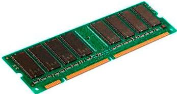
DRAM is a type of RAM module that stores each bit of data within a separate capacitor.  This is a proficient way to store the data in memory because it requires less physical space to store data.
DRAM can hold more amounts of data by a particular chip size. Capacitors in DRAM are need to be constantly recharged to keep their charge, thus, DRAM requires more power.
Dynamic Random Access Memory
Each DRAM memory chip consists of a storage location or memory cells.  It is made up of capacitor and transistor which can hold either active or inactive state. Each DRAM cell is referred to as a bit.
When DRAM cells are in active state, then charge is at high state. When DRAM cells are an  inactive state, then charge is below a certain level.

Cache Memory Orgonization:

Cache memory is a type of memory which is used to hold the frequently used data from main memory locations. The cache memory is placed close to the CPU. Cache memory starts from 00h to 0Fh. Cache memory is relatively small, consisted with 8k and 16k but it works effectively. It is a byte addressable memory and  it stores and remove only 1-bit of data. The cache memory filled from the main memory when CPUs require the instructions. The cache memory mainly used for reduce the average time to the access memory.

RAM Memory Organization and Its Types of Memory

RAM Memory Organization and Its Types of Memory

Memory is an important component of microcontrollers or CPUs for storing information that is used to controlelectronics projects. Internally, memory has been divided into several parts that consists of special types of registers those help to store data. There are two types of memories such as RAM memory and ROM memory, in many two are available in similar way. Here we will discuss about RAM memory organization of 8051 and its registers. This information is helpful for the embedded system designers to write program easily.
RAM Memory
RAM Memory

RAM Memory Organization of 8051 Microcontroller:

8051 microcontroller has 256 bytes of RAM memory, which is divided in two ways, such as 128 bytes for special function registers (SFR) and 128 bytes for general purpose memory. RAM memory organization contains a group ofgeneral purpose registers which are used to store information with a fixed memory address register, and SFR memory contains all peripheral related registers like ‘B’ register, Accumulator, Counters or Timers and interrupt related registers.

Remotely Controlled Android based Electronic Notice Board

Remotely Controlled Android based Electronic Notice Board
Notice Board is primary thing in any institution / organization or public utility places like bus stations, railway stations and parks. But sticking various notices day-to-day is a difficult process. A separate person is required to take care of this notices display. This project deals about an advanced hi-tech wireless notice board.
The main objective of the project is to develop a wireless  user’s android application device. Remote operation is achieved by any smart-phone/Tablet etc., with Android OS, upon a GUI (Graphical User Interface) based touch screen operation.
While the user sends the message from the android application device, it is received and retrieved by the Bluetooth device at the display unit. The Bluetooth access password will only be known to the  user. It is then sent to the microcontroller that further displays the notice sent from the user on to the electronic notice board which is equipped with a 16X2 LCD display. It uses a microcontroller from 8051 family.
The power supply consists of a step down transformer 230/12V, which steps down the voltage to 12V AC. This is converted to DC using a Bridge rectifier. The ripples are removed using a capacitive filter and it is then regulated to +5V using a voltage regulator 7805 which is required for the operation 
of the microcontroller and other components.

Circuit Diagram of Cell phone operated land rover Robotic Vehicle:

Circuit Diagram of Cell phone operated land rover Robotic Vehicle:

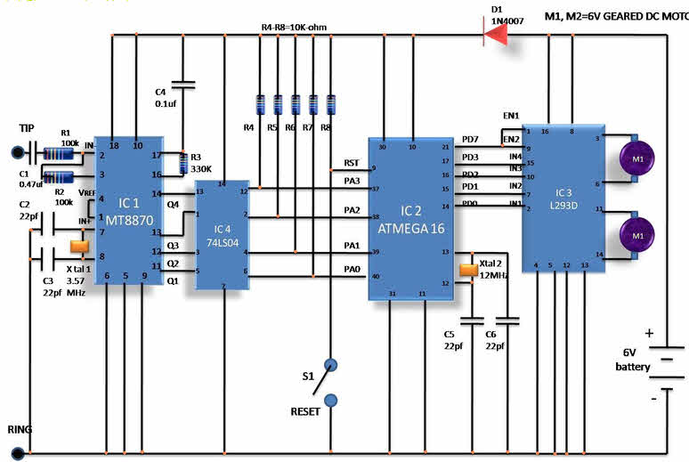
The main components of this cellphone-operated robotic landrover are microcontroller, motor driver and DTMF decoder. An MT8870 series DTMF decoder is used in this project which uses digital counting techniques to detect the 16 DTMF tone pairs into a 4-bit code output. The built- in dialtone circuit eliminates prefiltering. If an input signal is given at the pin2, then the input configuration is recognized to be effective. The 4-bit-decode signal of the DTMF tone is transferred to the pin11 through the pin 14′s output. These pins are connected to the microcontroller pins Pao, Pa1, Pa2 and Pa3. The output of the microcontroller from port pins PD0 through PD3 and PD7 are fed to the inputs IN1, IN4 and enables the pins EN1, EN2 of the motor-driver L293D IC to drive  the two DC motors.
Circuit Diagram of Cell phone Operated Land Rover
In this circuit, S1 switch is used for manual reset. The output of the microcontroller  is not enough to drive the DC motors, so current drivers are necessary for motor rotation.The  L293D  motor driver is designed to provide bidirectional drive currents of up to 600 mA at voltages from 4.5V to 36V, which makes it easier to drive the DC motors. The L293D motor driver consists of four drivers. The pins IN1 through IN4 & OUT1 and OUT4 are the input and output pins of the driver 1 through driver 4. The drivers 1,2,3 and 4 are enabled by the enable pin1(EN1) and the pin 9 (EN2). When enable input EN1 (pin1) is high, the drivers 1 and 2 are enabled. Similarly, the enable input EN2 (pin9) enables the drivers 3.

Advantages and Disadvantages:

The advantages of cellphone-operated-robotic landrover include wireless controlling provisioning and surveillance system, 3G-technology-based vehicle navigation, and limitless operational range based on the network of the cellphone. The disadvantage include: the cost as the cellphone billing is high; mobile batteries discharge : the discharging problem associated with the batteries as the batteries loss charge due to quick discharge because the load is high; adaptability: the system is not adaptable to all cellphones, but the ones with the headset attached can only be used.
Thus, this Cellphone-operated robot project is very useful in military applications to control military vehicles by using a mobile phone. In  future, we can detect the position of enemies by arranging a wireless camera to the land rover robotic vehicle. This project can  also be helpful in academics as students can learn various terminologies and principles proposed in this project. This project will help students add their innovative thoughts and ideas todevelop robotics projects.

Cell Phone Operated Land Rover Robotic Vehicle working with Block Diagram

Cell Phone Operated Land Rover Robotic Vehicle working with Block Diagram


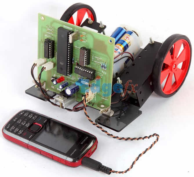
Cell phone Operated Land Rover Robotic Vehicle by Edgefxkits.com
Usually, remote control robots use RF circuits, which have the drawbacks of limited working range, limited control and limited frequency range. To overcome these drawbacks,cell phone operated land rover robotic vehicle is used. It provides the advantages of robotic control, intrusion free controllers and up to twelve controlling systems, etc.
Although the capabilities and appearance of embedded robotics vary vastly, all robots share the features of a movable, mechanical structure under some form of control. The control of robots involves three different phases they are perception, processing and action. Normally, the sensors are mounted on the robot. The perception and processing is done by the on-board microcontroller, and the action is performed using motors.

Cell Phone Operated Land Rover Robotic 

The main intention of this project is to control a robotic arm which is mounted on a robotic vehicle by using a mobile phone. It provides a large working range and robust control etc.

Block Diagram of Cell Phone Operated Land Rover Robotic Vehicle:

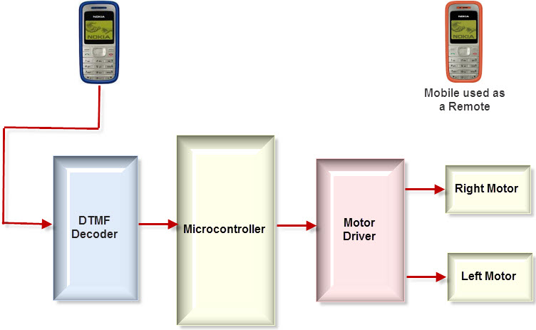
Block Diagram of Cell phone Operated Land Rover
The major building blocks are microcontroller, Cellphone, DTMF Decoder and DC-Motor-driver circuit. The cellphone is the most important part of the entire system because the entire system works and is activated by the cellphone. DTMF (dual tone multi frequency)  receives the input signal from cell phone and decode it, and then generates 4-bit-digital output of the 8051 microcontroller. When the DTMF decoder gives a digital output , it also generates an interrupt every time.
The microcontroller is the heart of the entire system as it performs the entire controlling actions. Microcontroller depends upon the code which is generated by the DTMF decoder to move the rover right or left and forward or backward by rotating both DC motors. The DC motor driver receives activating signals from the microcontroller in terms of low or high logic, then it amplifies and rotates two motors in both directions.
The control of robot involves mainly four different phases: perception, action processing and detection. In the perception stage if the cellphone attached to the robot receives a call, then the pressing action of the key on the cellphone decodes the generated DTMF tone. Then, the decoder chip receives the audio signal from the cellphone, and then converts the DTMF tone into a binary code, which is then fed to the microcontroller. In this project, an MT88710 IC is used as a DTMF decoder. In the processing stage, the microcontroller processes the binary code which is received from the DTMF decoder. The Microcontroller is preprogrammed in ‘C’ to perform this particular task according to  the input bits.
On the action stage, the rotation of the motors depends upon the input given by the microcontroller. Two DC motors each of 30 RPM are used for the landrover and are driven by the motor-driver IC. On detection the stage, and for obstacle detection, an infrared transmitter and receiver are used along with the buzzer. When the obstacle comes in front of the robot, the IR transmitter transmits the IR rays on the object, then the object reflects the IR rays to the IR receiver. The IR receiver then receives the IR rays to activate the buzzer.

Projects on Robotic Applications for Engineering Students

Projects on Robotic Applications for Engineering Students


In the area of robotics, it is important to deal with design, operation, construction, structural disposition, manufacture and application of robots. Using computer technology one can work on their control, sensory feedback, and information processing using appropriate hardware and sensors. Many motors are used in robotics which is controlled through dedicated micro-controllers with appropriate program. Therefore, language knowledge in assembly and ‘C’ is a must to design robotic applications.
Nowadays many engineering students showing lot of interest on robotics projects and they create lot of interest as compared to others. Robots such as line following, pick n place, firefighting, wall tracking, hexapod, humanoid etc are few popular projects in academic level.
Following are the few interesting Robotics Projects Ideas for final year engineering students:
  1. RF Controlled Robotic Vehicle with Laser Beam Arrangement - Abstract.
  2. Line Following Robotic Vehicle - Abstract.
  3. Pick & Place With Soft Catching Gripper – Abstract.
  4. Fire Fighting Robotic Vehicle using Microcontroller– Abstract.
  5. RF controlled robot with Night Vision Wireless Camera for Spying in War Field – Abstract.
  6. Microcontroller Based Line Following Robotic Vehicle– Abstract.
  7. Obstacle Avoidance Robotic Vehicle using Ultrasonic Sensor – Abstract.
  8. Auto Metro Train to Shuttle between Stations – Abstract.
  9. IR Controlled Robotic Vehicle – Abstract.
  10. Cell Phone Controlled Robotic Vehicle – Abstract.
  11. Metal Detector Robotic Vehicle – Abstract.
You may get the block diagram and output video details of the above projects along with the abstract by clicking on the “abstract” links.
Please check the below Robotics Live Projects
Line Following Robotic Vehicle
A Line Following Robot is a robot which follows a certain path on which it moves. The path can be a black path on a white floor or a magnetic field. These robots are being used in a variety of applications from being a guide at public places to automatic vehicles. Here a Line Following robotic vehicle is developed which is made to move on a curved black path sensed by a pair of sensors for each motor.
Here the robotic vehicle consists of two motors and the DC supply to each motor is controlled using a transistor which acts as a switch. A pair of sensors each comprising of an IR LED and a photodiode are placed beneath the circuit. The white floor is sensed by the sensors and the motors are given the rotation accordingly. At the turning, on encountering the black path, one of motors stop rotating with the sensor input. The sensor works on the principle that when light from the IR LED falls on the white surface it gets reflected and this reflected light when falls on the photodiode, reduces its resistance so as to control the conduction of the motor switch.
Metal Detector Robotic Vehicle
A robotic vehicle is designed which serves the purpose of detecting metals. Such robots can be used to detect landmines at places. Landmines are explosive devices which are placed under the ground and it is very dangerous to detect those manually using metal detectors. Here a metal detector is embedded to the robot circuit and the robot is controlled using RF communication.
At the transmitter side, number of push buttons is interfaced to the microcontroller to provide required motion to the robot. When any button is pressed the command is send to the microcontroller which delivers a binary data for the button and the parallel data is converted to serial data using encoder and this command is transmitted using RF module.
At the receiver side, this command is decoded by the Decoder and based on the command; microcontroller gives relevant signals to the motor driver to drive the two motors to give the robot the desired motion. A metal detector is embedded to the circuit which detects any metal and accordingly gives an indication using a buzzer.
Obstacle Avoidance Robotic Vehicle
A robot can be controlled either by detecting the environment on its own or manually using a remote or any other means. Here a fully automatic robot is developed which senses the area around it and accordingly moves. A sensor arrangement is embedded which senses any objects ahead of it and accordingly the robot changes its direction to avoid any collision. Such robotic vehicles can be used at places like sanctuaries etc.
Ultrasonic sensor is used to detect presence of any obstacle. These sensors work on the principle of reflection of ultrasonic waves by the objects which is received by the sensors and converted to electrical signals. On receiving any interruption signal, the microcontroller thus gives proper command to the motor driver such that one of the motor is stopped and other motor rotates, giving a change in direction to the robot.
Pick N Place Robotic Vehicle with Soft Catching Gripper
A robotic vehicle can be used to pick up objects and place it accordingly. For this purpose the robots consist of end effectors whose moment is controlled accordingly using motors. The robotic vehicle is controlled remotely by a set of buttons using RF communication.
At the transmitter side, a keypad is interfaced to the microcontroller and when a relevant key is pressed, the microcontroller generates a binary code for that key and this binary code is converted to serial form and sends through a RF module and an RF antenna.
At the receiver, two motors are used to give relevant motion to the robotic vehicle and another two motors are used to control the movement of the gripper to hold any object and place it on the desired place. The commands send from the transmitter are decoded and used by the microcontroller to give proper signals to the motor driver ICs.
RF Controlled Robotic Vehicle with LASER Beam Arrangement
One of the major applications of Robotics is in military. They can be used to survey enemy lands, detect and destroy targets.  A Robot can be embedded with a LASER gun which can emit strong focused monochromatic light that can actually harm the targets or produce a spot on the target to make them easier to be detected. Here a simple prototype of such a robotic vehicle is designed which is embedded with a LASER pen and controlled using RF communication.
War Field Spying Robot with Night Vision Camera
A robotic vehicle is designed which consists of a wireless camera that can take images even in dark and wireless transmit these images to a TV receiver unit. These robots are frequently used in military to spy on enemy lands and send the information to the controlling unit. Here this robot is controlled using RF communication by a set of push buttons.
Fire Fighting Robotic Vehicle
Robots can be used in many hazardous situations like when a fire accident occurs. Here such a prototype is demonstration which consists of a water pipe with a nozzle and a pump.  The movement of the robot as well the spraying of water by the nozzle is controlled remotely using a set of push buttons and the commands are transmitted the robot through RF communication.
Line Following Robotic Vehicle with Microcontroller
Here a line following robotic vehicle is designed which is controlled using a microcontroller. Here one pair of sensors are used to sense the path and based on the input, the microcontroller gives proper commands to the motor driver IC to drive the motors accordingly.
Touch Screen based Remote Controlled Robotic Vehicle for Stores Management
Here a pick and place robot is developed which is controlled using RF communication. A touch screen panel is used to give commands which are transmitted and received by the robot to give proper motion to the robot in the desired direction and control the pick and place operation.
Auto Metro Train that Shuttles between Two Stations
An automatic train is developed with automatic start and stop mechanism such that the train stops at a particular station and starts moving after a certain time. It also consists of a mechanism to automatically open and close the door and counts the number of persons entering the train.
List of some more robotics projects ideas for engineering students:
  • Accelerometer (Gyroscope) Controlled Robot
  • Radio Frequency (RF) Controlled Wireless Robot
  • Voice operated robot with speaker identification technology
  • Computer controlled Pic and Place Robot (wired or wireless)
  • Zigbee controlled Boat with wireless video and voice transmission with night vision capability
  • Autonomous Robot with artificial vision for obstacle detection
  • Smoke and LPG Gas detection robot with wireless control
  • Visible light follower Robot
  • Android mobile phone controlled bluetooth robot
  • Wireless operated War field spying Robot with night vision wireless camera
  • Construction of flying Quad Rotor Chopper with Video camera surveillance system
  • Digital Compass and GPS based self navigating Robot
  • Bomb detection Robot
  • DTMF based humanless Robotic boat control for ocean research application
  • Wifi robot controlled from Android smart mobile phone
  • Wireless room freshener spraying robot with video vision
  • DTMF based Mobile phone controlled Robot
  • flying Quad robot chopper with wireless video camera
  • GPS and Digital Compassed based self navigating robot
  • Bomb displacing robot with wireless video camera controlled form PC/Laptop
  • GSM (SMS) Mobile Phone Controlled Intelligent Robot
  • Wireless Voice and image transmission robot for surveillance system
  • Infrared Light tracing Robot (TV Remote controlled)
  • Live Human detection and alerting Robot
  • Micro Electro Mechanical Sensor (MEMS) Accelerometer/Gyroscope based self-balancing robot
  • Mobile phone Bluetooth operated robot
  • Mobile phone controlled four-legged walking robot with speed and direction control
  • Obstacle detection robot with mechanical sensing switches
  • Obstacle detection Robot with Ultrasonic Sensors
  • PC Controlled Wired Robot
  • Wireless operated war field land Rover that alerts on sensing planted Land Mines
  • Human-robot interface using robust speech recognition
  • PC controlled wireless Multipurpose robot
  • Wireless operated Fire extinguisher Robot with water jet spray
  • Remote Controlled Land Rover
  • Robot Controlled Wireless Audio-Video Streaming Camera
  • Servo motor controlled wireless video camera control system
  • Wall Follower Robot
  • speech controlled wireless elevator system
  • Speech recognition robot with ultrasonic obstacle avoidance system
  • Touch Screen Controlled intelligent robot
  • Voice operated Intelligent Fire extinguisher vehicle