Cell Phone Operated Land Rover Robotic Vehicle working with Block Diagram
Usually, remote control robots use RF circuits, which have the drawbacks of limited working range, limited control and limited frequency range. To overcome these drawbacks,cell phone operated land rover robotic vehicle is used. It provides the advantages of robotic control, intrusion free controllers and up to twelve controlling systems, etc.
Although the capabilities and appearance of embedded robotics vary vastly, all robots share the features of a movable, mechanical structure under some form of control. The control of robots involves three different phases they are perception, processing and action. Normally, the sensors are mounted on the robot. The perception and processing is done by the on-board microcontroller, and the action is performed using motors.
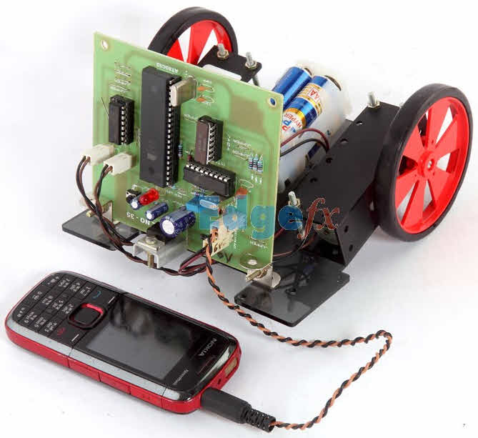
Cell Phone Operated Land Rover Robotic
The main intention of this project is to control a robotic arm which is mounted on a robotic vehicle by using a mobile phone. It provides a large working range and robust control etc.
Block Diagram of Cell Phone Operated Land Rover Robotic Vehicle:
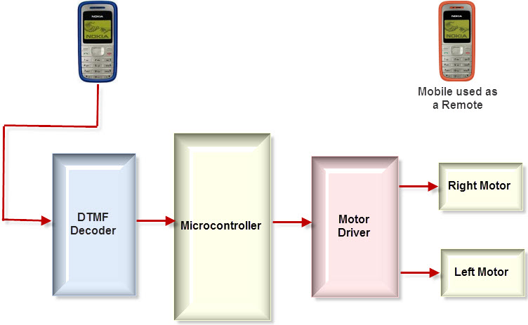
Block Diagram of Cell phone Operated Land Rover
The major building blocks are microcontroller, Cellphone, DTMF Decoder and DC-Motor-driver circuit. The cellphone is the most important part of the entire system because the entire system works and is activated by the cellphone. DTMF (dual tone multi frequency) receives the input signal from cell phone and decode it, and then generates 4-bit-digital output of the 8051 microcontroller. When the DTMF decoder gives a digital output , it also generates an interrupt every time.
The microcontroller is the heart of the entire system as it performs the entire controlling actions. Microcontroller depends upon the code which is generated by the DTMF decoder to move the rover right or left and forward or backward by rotating both DC motors. The DC motor driver receives activating signals from the microcontroller in terms of low or high logic, then it amplifies and rotates two motors in both directions.
The control of robot involves mainly four different phases: perception, action processing and detection. In the perception stage if the cellphone attached to the robot receives a call, then the pressing action of the key on the cellphone decodes the generated DTMF tone. Then, the decoder chip receives the audio signal from the cellphone, and then converts the DTMF tone into a binary code, which is then fed to the microcontroller. In this project, an MT88710 IC is used as a DTMF decoder. In the processing stage, the microcontroller processes the binary code which is received from the DTMF decoder. The Microcontroller is preprogrammed in ‘C’ to perform this particular task according to the input bits.
On the action stage, the rotation of the motors depends upon the input given by the microcontroller. Two DC motors each of 30 RPM are used for the landrover and are driven by the motor-driver IC. On detection the stage, and for obstacle detection, an infrared transmitter and receiver are used along with the buzzer. When the obstacle comes in front of the robot, the IR transmitter transmits the IR rays on the object, then the object reflects the IR rays to the IR receiver. The IR receiver then receives the IR rays to activate the buzzer.
No comments:
Post a Comment